Build a better slow crawl

SCX30 Brushless Upgrades,
All Inclusive.

Six conversion paths. The parts they need. A clear way to choose, buy and set up your next upgrade.

Compare the six builds
Axial SCX30 vehicle lineup: Ford Bronco, Chevrolet K10, Jeep Wrangler JLU, Jeep CJ-7 GenRight, and Toyota Tacoma TRD Pro

Start with the tools you need.

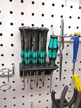
For small cross-head screws

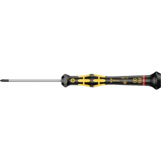
Wera Kraftform Micro 2050 PH00 precision Phillips screwdriver

Wera PH00 precision Phillips screwdriver

PH00 is the curated starting point. Some tiny recesses need PH000 instead: use a tip that seats fully without wobbling, and keep powered drivers away from tiny hardware. Amazon links to the genuine Wera driver; AliExpress links to a compatible unbranded alternative.
For 0.050-inch hex screws

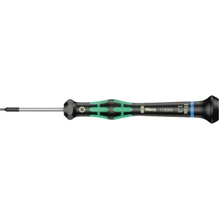
Wera Kraftform Micro 2054 0.050 inch hex screwdriver

Wera 2054 · exact 0.050″ hex driver

An optional comfort upgrade when your hardware uses 0.050-inch hex. This is 1.27 mm; a 1.3 mm driver is not the same exact size. Amazon links to the genuine Wera 2054; AliExpress links to a compatible unbranded alternative.
Wheel tools and a place for small parts
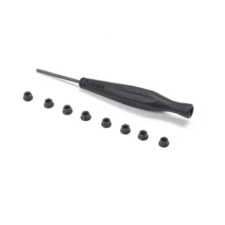
Axial SCX30 wheel nuts and wheel nut tool AXI-3328

Axial wheel nuts & wheel-nut tool · AXI-3328

Reuse your original wheel tool if you still have it. The Axial replacement listing includes wheel nuts and the tool.

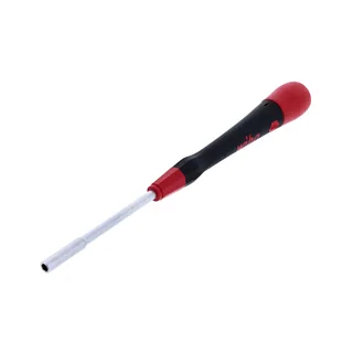
Wiha 26583 PicoFinish 3 mm precision nut driver

Wiha 26583 PicoFinish · 3 mm nut driver

Optional for repeated wheel removal. Owners report using 3 mm on the original wheel nuts; check that the driver fits without slipping. Amazon links to the genuine Wiha 26583; AliExpress links to a compatible unbranded alternative.
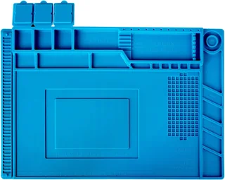
Keep small parts together

S-160 silicone work mat with compartments for screws and small parts

S-160 silicone work mat

Compartments keep screws, nuts and pins in one place. A tray you already own works too.

Axial AXI-3331 SCX30 replacement screw set

Axial SCX30 replacement screw set

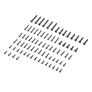
Axial AXI-3331 replacement hardware for a missing or damaged screw.

Choose your path

Compare the six builds.

Priority
Tuning

6 setups

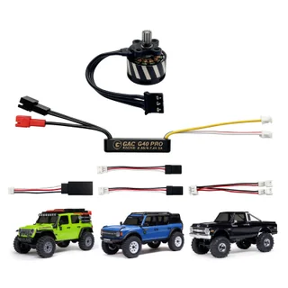
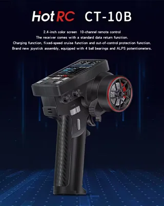
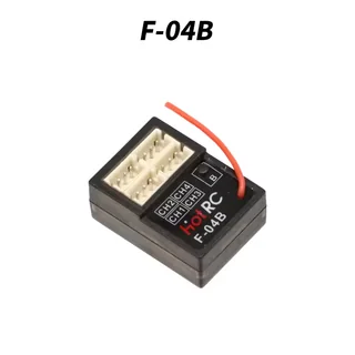
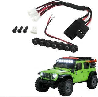
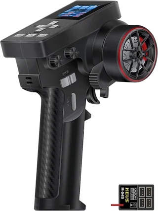
GACRacing G40 PRO ESC and GM1614 outrunner power system for SCX30HotRC CT-10B 10-channel transmitter with 8 model memoryHotRC F-04B 4-channel micro receiver with binding buttonSCX30 roof LED light bar and factory-light pass-through wiring harness

GACRacing G40 Pro + GM1614

Approx. build cost$95–$150Build parts · USD
Controller & receiver
Choose HotRC or MEUS below
Lights
Add the SCX30 light harness
Electronics
Separate ESC and receiver
Water protection
IP67 waterproof & dustproof
Tuning
Phone app
Motor + ESC
View parts & setup

The motor, ESC and receiver remain separate, with phone tuning on the ESC. Add the lighting harness and route its pass-through lead to the receiver.

Main conversion

GACRacing G40 PRO ESC and GM1614 outrunner power system for SCX30

GACRacing GM1614 + G40 Pro SCX30 power system

Choose one matched radio system

AliExpress: transmitter and matching receiver. Amazon: the alternative radio/receiver bundle. You do not need both routes.

HotRC route · two purchases
MEUS route · one bundle
MEUS ME-8B transmitter and M-04B micro receiver bundle

MEUS ME-8B transmitter + M-04B receiver (Amazon USA)

Check the selected receiver version and included adapter leads.

Lighting, adapters & mounting

Install without soldering · 7 steps
Before you start
  • Remove the stock motor screws carefully and retain the original hardware.
  • Verify battery plug, signal adapters, lighting harness socket type and BEC voltage before buying.
  • Keep the SCX30 stock motor, receiver and lights until the conversion passes its first test.
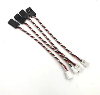
Battery → ESC → motor. Receiver channels: CH1 is Steering (stock servo), CH2 is Throttle (ESC signal), CH3 is Lights. MEUS ME-8B includes 4 adapter leads in the box: connect servo to CH1, ESC throttle to CH2, and light kit to CH3 for independent transmitter light switching. For HotRC builds without adapter cables, use the light harness workaround (servo into harness pass-through, then via JR female to ZH 1.5mm adapter into CH1 for steering and lights together). G40 Pro BEC is app-selectable: set 6 V for stock servo, 7.4 V for HV upgrade servos.
  1. Make a photo first

    Photograph the stock receiver, battery polarity and both light plugs before removing anything. Disconnect the battery.

  2. Remove the original electronics

    Remove the stock motor screws carefully. Mount the replacement motor with the screws supplied in its kit. Keep the original screws together.

  3. Fit the new motor and set gear mesh

    Use the supplied 11T / 0.3 MOD pinion. Keep the motor wires clear of the spur gear. Follow the gear mesh check below before securing motor screws.

    Brushless Motor Gear Mesh Check

    Before tightening motor mount screws or driving, check gear mesh with two simple tests:

    1. Paper strip test: Feed a narrow strip of standard notebook paper between the motor pinion and spur gear while rotating the spur by hand. The paper should come out with clean accordion crinkles, not pinched flat, torn, or cut in half.

    2. Backlash check: Gently rock the spur gear back and forth with your fingertip. You should feel a tiny hair of play (backlash) without moving the motor pinion. Check this across a full 360-degree rotation of the spur to ensure there are no tight spots due to gear eccentricity.

    Warning: Too tight causes motor overheating, gear binding, and rapid battery drain. Too loose will strip the 0.3 MOD pinion or spur teeth under crawling load.

    RC motor gear mesh check

    Check motor gear mesh with the paper strip test and backlash check across 360 degrees to prevent gear strip or overheating

    Watch on YouTube
  4. Wire receiver: CH1 steering, CH2 throttle, CH3 lights

    Standard channel layout: CH1 is Steering, CH2 is Throttle, CH3 is Lights. If using MEUS ME-8B, use the included adapter cables to connect steering to CH1, G40 Pro throttle to CH2, and light kit to CH3 for direct radio light switching. If using HotRC without adapters, use the JR female to ZH 1.5mm workaround on CH1 for steering and lights together; plug G40 Pro throttle into CH2.

  5. Connect the lights without soldering

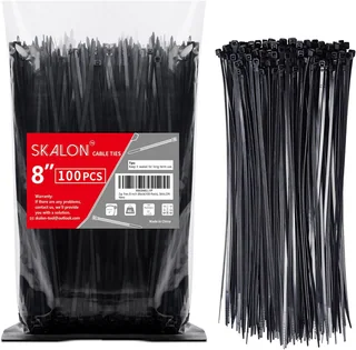
    For MEUS ME-8B builds: use the 4 adapter cables included in the box. One adapter connects the stock 3-pin steering servo directly to CH1 (Steering), a second connects the ESC throttle lead directly to CH2 (Throttle), and a third adapter connects the light kit directly into Channel 3 (CH3). This enables direct transmitter on/off light control without needing the CH1 pass-through method. For HotRC builds (or receivers without adapter cables): use the light harness workaround. Plug stock headlights into the harness and steering servo into the pass-through socket, then connect to CH1 via a JR female to ZH 1.5mm adapter (powers both steering and lights constantly on CH1). Connect ESC throttle to CH2. Align polarity and secure excess wires with cable ties. Keeping factory bumper headlights requires zero body modifications; mounting the optional roof light bar requires drilling two small holes in the body for its screws.

  6. Bind the radio and calibrate throttle

    Choose one radio bundle: HotRC CT-10B plus its matching micro receiver from AliExpress, OR MEUS ME-8B with its micro receiver from Amazon. For CT-10B use its pairing menu and the receiver BIND button. For ME-8B use its radio Bind menu and the M-04B receiver BIND button. Confirm a steady link indicator before testing.

    GACRacing G40 Pro Throttle Calibration

    The G40 Pro uses smartphone app-based calibration:

    1. Turn on transmitter and power on the truck.
    2. Open the GACRacing app on your phone and connect via Bluetooth.
    3. Select throttle calibration in the app menu and follow on-screen prompts for neutral and full throttle range.
    4. Test forward and reverse; if reversed, toggle the motor rotation setting in the app.
  7. Test before closing the body

    With wheels off the ground: verify neutral stop, steering direction, forward/reverse, headlights, and radio failsafe. To test failsafe, switch transmitter off briefly with wheels off the ground; the motor must stop immediately. Check cable clearance and ESC warmth. Only then tie up wires and close the chassis.

SCX30 motor and ESC removal

Shows a different brushless system; use for the mechanical layout, not the exact connectors

Watch on YouTube
CT-10B receiver binding

Shows an F-10A receiver; follow your micro receiver’s own BIND-button location

Watch on YouTube
Keep the factory lights

Add the SCX30 lighting harness for the modular builds (on the Amazon GOUPRC GP-M32, headlights and taillights can plug directly into the ESC’s HL and TL sockets). Keep the factory lights; mounting the optional roof bar adds body work.

MEUS radio route

Check which receiver and adapter leads your chosen bundle actually includes. Use its documented servo, throttle and lighting sockets.

MEUS ME-8B receiver adapter & CH3 light install

Watch Work Hard RC connect SCX30 electronics using the adapter cables in the MEUS ME-8B box (CH1 steering, CH2 throttle, and CH3 direct transmitter light control)

Watch on YouTube

HotRC radio route

The reference build uses a micro receiver and adapter for the harness pass-through. Match the receiver socket and pin order; buy the transmitter and its matching receiver together.

HotRC light harness install with adapter

Watch Bucketlist R/C install the SCX30 light bar into a micro receiver using a standard servo to ZH 1.5mm conversion adapter

Watch on YouTube

The receiver version determines which adapters you need. Check the pack included with your chosen radio bundle.

Technical specifications
Battery voltage
2S–3S LiPo7.4–11.1 V nominal
ESC current
40 A advertised
Motor
GM16143500 / 7500 KV options
Servo power (BEC)
6 / 7.4 V5 A maximum

2S and 3S describe the battery voltage. BEC is the separate power supply for the receiver and servo. Keep the factory servo within 4.8–6 V; the setup steps show the setting for this ESC.

The SCX30 G40 Pro and GM1614 combination. Select the motor KV option before ordering.

The 40 A figure is the manufacturer’s advertised rating. It does not identify a continuous or peak rating.

Crawling control
FOC motor control
ESC water protection
IP67 waterproof & dustproof
Understand this conversion

GACRacing sells the SCX30-specific GM1614 motor and G40 Pro ESC together. They are separate components, with Bluetooth settings handled by the G40 Pro. The radio system in this build comes from HotRC rather than GACRacing.

GACRacing power-system instructions
Read owner discussions

Owners compare app-tunable controllers with simpler lower-cost kits. This setup gives you separate motor, ESC and radio components, plus adjustments through GACRacing’s app.

Open the owner discussion
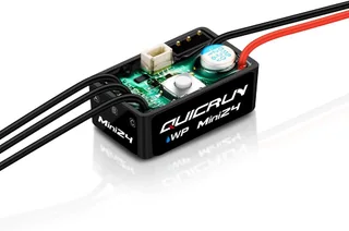
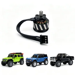
Hobbywing QuicRun WP Mini24 waterproof micro brushless ESCGACRacing GM1614 brushless outrunner motor with 11T 0.3 mod pinionHotRC CT-10B 10-channel transmitter with 8 model memoryHotRC F-04B 4-channel micro receiver with binding button

Hobbywing WP Mini24 + GM1614

Approx. build cost$110–$150Build parts · USD
Controller & receiver
Choose HotRC or MEUS below
Lights
Add the SCX30 light harness
Electronics
Separate ESC and receiver
Water protection
IP67 waterproof & dustproof
Tuning
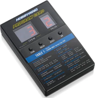
Programming card
View parts & setup

ESC, motor and radio system are separately replaceable. Use JR-to-micro adapters for the ESC throttle lead and servo/lighting connection, then calibrate the WP Mini24 using its ON/OFF button.

Main conversion

GACRacing GM1614 brushless outrunner motor with 11T 0.3 mod pinion

GACRacing GM1614 SCX30 outrunner with 11T pinion

Choose one matched radio system

AliExpress: transmitter and matching receiver. Amazon: the alternative radio/receiver bundle. You do not need both routes.

HotRC route · two purchases
MEUS route · one bundle
MEUS ME-8B transmitter and M-04B micro receiver bundle

MEUS ME-8B transmitter + M-04B receiver (Amazon USA)

Check the selected receiver version and included adapter leads.

Lighting, adapters & mounting

Install without soldering · 7 steps
Before you start
  • Remove the stock motor screws carefully and retain the original hardware.
  • Verify battery plug, signal adapters, lighting harness socket type and BEC voltage before buying.
  • Keep the SCX30 stock motor, receiver and lights until the conversion passes its first test.
Battery → ESC → motor. Receiver channels: CH1 is Steering (stock servo), CH2 is Throttle (ESC signal), CH3 is Lights. MEUS ME-8B includes 4 adapter leads in the box: connect servo to CH1, ESC throttle to CH2, and light kit to CH3 for independent transmitter light switching. For HotRC builds without adapter cables, use the light harness workaround (servo into harness pass-through, then via JR female to ZH 1.5mm adapter into CH1 for steering and lights together). WP Mini24 switch-mode BEC is jumper/card selectable: keep 6 V for stock servo, 7.4 V for HV upgrade servos.
  1. Make a photo first

    Photograph the stock receiver, battery polarity and both light plugs before removing anything. Disconnect the battery.

  2. Remove the original electronics

    Remove the stock motor screws carefully. Mount the replacement motor with the screws supplied in its kit. Keep the original screws together.

  3. Fit the new motor and set gear mesh

    Use the supplied 11T / 0.3 MOD pinion. Keep the motor wires clear of the spur gear. Follow the gear mesh check below before securing motor screws.

    Brushless Motor Gear Mesh Check

    Before tightening motor mount screws or driving, check gear mesh with two simple tests:

    1. Paper strip test: Feed a narrow strip of standard notebook paper between the motor pinion and spur gear while rotating the spur by hand. The paper should come out with clean accordion crinkles, not pinched flat, torn, or cut in half.

    2. Backlash check: Gently rock the spur gear back and forth with your fingertip. You should feel a tiny hair of play (backlash) without moving the motor pinion. Check this across a full 360-degree rotation of the spur to ensure there are no tight spots due to gear eccentricity.

    Warning: Too tight causes motor overheating, gear binding, and rapid battery drain. Too loose will strip the 0.3 MOD pinion or spur teeth under crawling load.

    RC motor gear mesh check

    Check motor gear mesh with the paper strip test and backlash check across 360 degrees to prevent gear strip or overheating

    Watch on YouTube
  4. Wire receiver: CH1 steering, CH2 throttle, CH3 lights

    Standard channel layout: CH1 is Steering, CH2 is Throttle, CH3 is Lights. If using MEUS ME-8B, use the 4 adapter cables included in the box: connect the stock 3-pin steering servo to CH1, the WP Mini24 throttle lead to CH2, and the light kit to CH3 for independent transmitter light switching (zero extra adapters needed). If using HotRC without adapter cables, use the JR female to ZH 1.5mm adapter workaround on CH1 (connecting steering and lights together through the harness pass-through), plus a second adapter for the WP Mini24 throttle lead on CH2.

  5. Connect the lights without soldering

    For MEUS ME-8B builds: use the 4 adapter cables included in the box. One adapter connects the stock 3-pin steering servo directly to CH1 (Steering), a second connects the ESC throttle lead directly to CH2 (Throttle), and a third adapter connects the light kit directly into Channel 3 (CH3). This enables direct transmitter on/off light control without needing the CH1 pass-through method. For HotRC builds (or receivers without adapter cables): use the light harness workaround. Plug stock headlights into the harness and steering servo into the pass-through socket, then connect to CH1 via a JR female to ZH 1.5mm adapter (powers both steering and lights constantly on CH1). Connect ESC throttle to CH2. Align polarity and secure excess wires with cable ties. Keeping factory bumper headlights requires zero body modifications; mounting the optional roof light bar requires drilling two small holes in the body for its screws.

  6. Bind the radio and calibrate throttle

    Choose one radio bundle: HotRC CT-10B plus its matching micro receiver from AliExpress, OR MEUS ME-8B with its micro receiver from Amazon. For CT-10B use its pairing menu and the receiver BIND button. For ME-8B use its radio Bind menu and the M-04B receiver BIND button. Confirm a steady link indicator before testing.

    Hobbywing WP Mini24 Throttle Calibration

    Follow this exact sequence to match your radio throttle to the ESC using the ESC’s ON/OFF button:

    1. Set transmitter throttle travel to 100% and trim to zero. Leave trigger at neutral.
    2. With ESC off and battery connected, hold ESC ON/OFF button until red LED flashes and beeps; release.
    3. Neutral: Press ON/OFF button once 1 green flash & beep
    4. Full Throttle: Pull trigger to full throttle → press ON/OFF 2 green flashes
    5. Full Brake: Push trigger to full reverse/brake → press ON/OFF 3 green flashes
    Hobbywing WP Mini24 calibration

    Watch the official Hobbywing calibration tutorial for throttle neutral, full throttle, and full brake endpoints

    Watch on YouTube
  7. Test before closing the body

    With wheels off the ground: verify neutral stop, steering direction, forward/reverse, headlights, and radio failsafe. To test failsafe, switch transmitter off briefly with wheels off the ground; the motor must stop immediately. Check cable clearance and ESC warmth. Only then tie up wires and close the chassis.

SCX30 motor and ESC removal

Shows a different brushless system; use for the mechanical layout, not the exact connectors

Watch on YouTube
CT-10B receiver binding

Shows an F-10A receiver; follow your micro receiver’s own BIND-button location

Watch on YouTube
Keep the factory lights

Add the SCX30 lighting harness for the modular builds (on the Amazon GOUPRC GP-M32, headlights and taillights can plug directly into the ESC’s HL and TL sockets). Keep the factory lights; mounting the optional roof bar adds body work.

MEUS radio route

Check which receiver and adapter leads your chosen bundle actually includes. Use its documented servo, throttle and lighting sockets.

MEUS ME-8B receiver adapter & CH3 light install

Watch Work Hard RC connect SCX30 electronics using the adapter cables in the MEUS ME-8B box (CH1 steering, CH2 throttle, and CH3 direct transmitter light control)

Watch on YouTube

HotRC radio route

The reference build uses a micro receiver and adapter for the harness pass-through. Match the receiver socket and pin order; buy the transmitter and its matching receiver together.

HotRC light harness install with adapter

Watch Bucketlist R/C install the SCX30 light bar into a micro receiver using a standard servo to ZH 1.5mm conversion adapter

Watch on YouTube

The receiver version determines which adapters you need. Check the pack included with your chosen radio bundle.

Technical specifications
Battery voltage
2S–3S LiPo7.4–11.1 V nominal
ESC current
25 A continuous60 A peak
Motor
GM16143500 / 7500 KV options
Servo power (BEC)
6 / 7.4 V2 A continuous

2S and 3S describe the battery voltage. BEC is the separate power supply for the receiver and servo. Keep the factory servo within 4.8–6 V; the setup steps show the setting for this ESC.

The WP Mini24 ESC with GM1614 motor. The motor and mounting are separate purchases.

Crawling control
FOC motor control
ESC water protection
IP67 waterproof & dustproof
Understand this conversion

Hobbywing is a brushless electronics manufacturer founded in 2005; its QuicRun WP Mini24 ESC is sold as a separate programmable controller. Here it is paired with GACRacing’s GM1614 motor and HotRC’s radio/receiver.

Hobbywing WP Mini24 manual (PDF)
Read owner discussions

Owners who assemble separate ESC and radio systems value the freedom to replace components later, even if the initial wiring takes more time.

Open the owner discussion
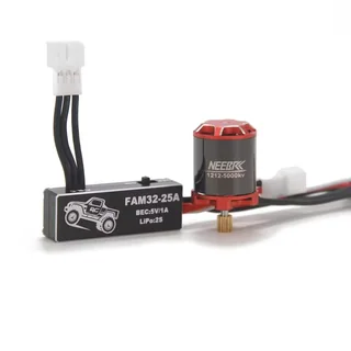
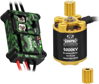
GOUPRC GP-M32 / FAM32 ESC and 1212 brushless motorHotRC CT-10B 10-channel transmitter with 8 model memoryHotRC F-04B 4-channel micro receiver with binding buttonSCX30 roof LED light bar and factory-light pass-through wiring harness

GOUPRC / FAM32 + 1212 Motor

Approx. build cost$80–$115Build parts · USD
Controller & receiver
Choose HotRC or MEUS below
Lights
Plug-and-play sockets on ESC
Electronics
Separate ESC and receiver
Water protection
Not rated
View parts & setup

The motor, ESC and radio receiver are separately replaceable. Amazon supplies the switched GOUPRC GP-M32 (30A/80A, 5V/3A BEC, dual light sockets) while AliExpress supplies the compact FAM32 25A.

Main conversion

Amazon optionDirect HL/TL light plugs
GOUPRC GP-M32 ESC and 1212 brushless motor combo (Amazon)
GOUPRC GP-M32 + 1212 Motor Combo

30A continuous / 80A peak. Features dedicated plug-and-play sockets for factory headlights and taillights.

AliExpress optionCompact crawler ESC
FAM32 ESC and 1212 brushless motor combo (AliExpress)
FAM32 + 1212 Motor Combo

25A continuous / 60A peak. Lightweight AM32 crawler combo. Connect lights via receiver channel or light harness.

Choose one matched radio system

AliExpress: transmitter and matching receiver. Amazon: the alternative radio/receiver bundle. You do not need both routes.

HotRC route · two purchases
MEUS route · one bundle
MEUS ME-8B transmitter and M-04B micro receiver bundle

MEUS ME-8B transmitter + M-04B receiver (Amazon USA)

Check the selected receiver version and included adapter leads.

Lighting, adapters & mounting

Install without soldering · 7 steps
Before you start
  • Remove the stock motor screws carefully and retain the original hardware.
  • Verify battery plug, signal adapters, lighting harness socket type and BEC voltage before buying.
  • Keep the SCX30 stock motor, receiver and lights until the conversion passes its first test.
Battery → ESC → motor. Receiver channels: CH1 is Steering (stock servo), CH2 is Throttle (ESC signal), CH3 is Lights. MEUS ME-8B includes 4 adapter leads in the box: connect servo to CH1, ESC throttle to CH2, and light kit to CH3 for independent transmitter light switching. For HotRC builds without adapter cables, use the light harness workaround (servo into harness pass-through, then via JR female to ZH 1.5mm adapter into CH1 for steering and lights together). 5.0 V linear BEC powers receiver and stock servo.
  1. Make a photo first

    Photograph the stock receiver, battery polarity and both light plugs before removing anything. Disconnect the battery.

  2. Remove the original electronics

    Remove the stock motor screws carefully. Mount the replacement motor with the screws supplied in its kit. Keep the original screws together.

  3. Fit the new motor and set gear mesh

    Use the supplied 11T / 0.3 MOD pinion. Keep the motor wires clear of the spur gear. Follow the gear mesh check below before securing motor screws.

    Brushless Motor Gear Mesh Check

    Before tightening motor mount screws or driving, check gear mesh with two simple tests:

    1. Paper strip test: Feed a narrow strip of standard notebook paper between the motor pinion and spur gear while rotating the spur by hand. The paper should come out with clean accordion crinkles, not pinched flat, torn, or cut in half.

    2. Backlash check: Gently rock the spur gear back and forth with your fingertip. You should feel a tiny hair of play (backlash) without moving the motor pinion. Check this across a full 360-degree rotation of the spur to ensure there are no tight spots due to gear eccentricity.

    Warning: Too tight causes motor overheating, gear binding, and rapid battery drain. Too loose will strip the 0.3 MOD pinion or spur teeth under crawling load.

    RC motor gear mesh check

    Check motor gear mesh with the paper strip test and backlash check across 360 degrees to prevent gear strip or overheating

    Watch on YouTube
  4. Wire receiver: CH1 steering, CH2 throttle, CH3 lights

    Standard channel layout: CH1 is Steering, CH2 is Throttle, CH3 is Lights. If using MEUS ME-8B, use the included adapter cables to connect steering to CH1, ESC throttle to CH2, and light kit to CH3. If using HotRC, use the JR female to ZH 1.5mm adapter workaround on CH1 for steering and lights together; plug ESC throttle into CH2.

  5. Connect the lights without soldering

    The GOUPRC GP-M32 ESC includes dedicated HL and TL sockets for direct plug-and-play headlight and taillight connection without an extra harness. For FAM32 or separate receivers with MEUS ME-8B: use the 4 adapter cables in the box to connect lights directly into CH3. For HotRC builds: plug headlights into the harness and steering servo into the pass-through socket, connected to CH1 via JR-to-ZH 1.5mm adapter.

  6. Bind the radio and calibrate throttle

    Choose one radio bundle: HotRC CT-10B plus its matching micro receiver from AliExpress, OR MEUS ME-8B with its micro receiver from Amazon. For CT-10B use its pairing menu and the receiver BIND button. For ME-8B use its radio Bind menu and the M-04B receiver BIND button. Confirm a steady link indicator before testing.

    Standalone ESC Throttle Setup

    Turn on transmitter with throttle at neutral, then power on the ESC. Listen for confirmation beeps indicating cell count and arming before driving. Check the included ESC manual for neutral and endpoint learning steps.

  7. Test before closing the body

    With wheels off the ground: verify neutral stop, steering direction, forward/reverse, headlights, and radio failsafe. To test failsafe, switch transmitter off briefly with wheels off the ground; the motor must stop immediately. Check cable clearance and ESC warmth. Only then tie up wires and close the chassis.

SCX30 motor and ESC removal

Shows a different brushless system; use for the mechanical layout, not the exact connectors

Watch on YouTube
CT-10B receiver binding

Shows an F-10A receiver; follow your micro receiver’s own BIND-button location

Watch on YouTube
Keep the factory lights

MEUS radio route

Check which receiver and adapter leads your chosen bundle actually includes. Use its documented servo, throttle and lighting sockets.

MEUS ME-8B receiver adapter & CH3 light install

Watch Work Hard RC connect SCX30 electronics using the adapter cables in the MEUS ME-8B box (CH1 steering, CH2 throttle, and CH3 direct transmitter light control)

Watch on YouTube

HotRC radio route

The reference build uses a micro receiver and adapter for the harness pass-through. Match the receiver socket and pin order; buy the transmitter and its matching receiver together.

HotRC light harness install with adapter

Watch Bucketlist R/C install the SCX30 light bar into a micro receiver using a standard servo to ZH 1.5mm conversion adapter

Watch on YouTube

The receiver version determines which adapters you need. Check the pack included with your chosen radio bundle.

Technical specifications
Battery voltage
2S LiPo7.4 V nominal
ESC current
25 A
Motor
1621 (1212) outrunner5000 KV
Servo power (BEC)
5 V1 A

2S and 3S describe the battery voltage. BEC is the separate power supply for the receiver and servo. Keep the factory servo within 4.8–6 V; the setup steps show the setting for this ESC.

Amazon supplies the GOUPRC GP-M32 combo (30 A cont, 80 A peak, 5 V / 3 A BEC, plug-and-play HL/TL light sockets, 1621/1212 5000KV 14-pole motor). AliExpress supplies the 25 A FAM32 ESC. Both use 5000 KV outrunner motors.

Understand this conversion

This modular conversion kit supplies a separate brushless motor and ESC. Amazon offers the GOUPRC GP-M32 combo with dual light ports and an ON/OFF switch; AliExpress offers the compact FAM32 package. Add a HotRC or MEUS radio bundle to complete the setup.

Selected motor and ESC listing
Read owner discussions

Owners have reported strong value and improved slow-speed control from low-cost SCX30 brushless kits. The most common installation advice is to organize the micro connectors and wires before closing the body.

Open the owner discussion
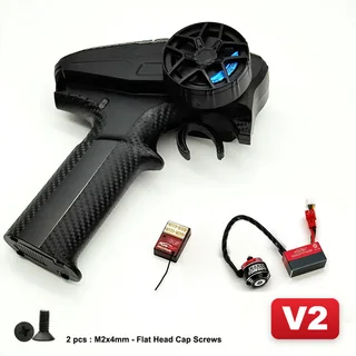
Furitek NanoModo full brushless control system with Gripor V2 radio

Furitek NanoModo FUR-2739

Approx. build cost$120Build parts · USD
Controller & receiver
Included in kit
Lights
Connect with the included lead
Electronics
Motor and ESC arrive wired together
Water protection
Not rated
Tuning
Phone app
Shop the kit
View parts & setup

The ESC and motor have separate housings, but current reported batches arrive with the motor and ESC leads joined rather than a convenient unplugging connector. Replacing one alone may require specialist wiring, so do not treat them as plug-swappable.

Main conversion

Furitek NanoModo full brushless control system with Gripor V2 radio

Furitek NanoModo FUR-2739 full control system

Lighting, adapters & mounting

Install without soldering · 7 steps
Before you start
  • Remove the stock motor screws carefully and retain the original hardware.
  • Verify battery plug, signal adapters, lighting harness socket type and BEC voltage before buying.
  • Keep the SCX30 stock motor, receiver and lights until the conversion passes its first test.
Battery → NanoPython ESC ↔ prewired NanoKomodo motor. Receiver channels: CH1 = Steering servo; CH2 = Throttle (NanoPython ESC signal). Join both stock light plugs through the included Y-lead into the matching powered micro port. NanoPython BEC defaults to 5.5 V (keep at 5.5 V for stock servo, switch to 7.4 V in app for HV servos).
  1. Make a photo first

    Photograph the stock receiver, battery polarity and both light plugs before removing anything. Disconnect the battery.

  2. Remove the original electronics

    Remove the stock motor screws carefully. Mount the replacement motor with the screws supplied in its kit. Keep the original screws together.

  3. Fit the new motor and set gear mesh

    Use the supplied 11T / 0.3 MOD pinion. Keep the motor wires clear of the spur gear. Follow the gear mesh check below before securing motor screws.

    Brushless Motor Gear Mesh Check

    Before tightening motor mount screws or driving, check gear mesh with two simple tests:

    1. Paper strip test: Feed a narrow strip of standard notebook paper between the motor pinion and spur gear while rotating the spur by hand. The paper should come out with clean accordion crinkles, not pinched flat, torn, or cut in half.

    2. Backlash check: Gently rock the spur gear back and forth with your fingertip. You should feel a tiny hair of play (backlash) without moving the motor pinion. Check this across a full 360-degree rotation of the spur to ensure there are no tight spots due to gear eccentricity.

    Warning: Too tight causes motor overheating, gear binding, and rapid battery drain. Too loose will strip the 0.3 MOD pinion or spur teeth under crawling load.

    RC motor gear mesh check

    Check motor gear mesh with the paper strip test and backlash check across 360 degrees to prevent gear strip or overheating

    Watch on YouTube
  4. Wire receiver: CH1 steering, CH2 throttle, CH3 lights

    Plug the stock steering servo into CH1 (Steering) and the pre-wired NanoPython ESC throttle lead into CH2 (Throttle). Join stock headlight plugs via the included Y-lead into the receiver.

  5. Connect the lights without soldering

    NanoModo includes a Y-lead that joins both stock light plugs to one ZH-1.5 receiver connector. Align the power and ground pins; the signal pin remains unused.

  6. Bind the radio and calibrate throttle

    The Gripor V2 transmitter and receiver are supplied together. Turn on the radio and connect the ESC; follow the Gripor V2 BIND procedure if pairing is needed.

    Furitek NanoPython Throttle Calibration

    Furitek uses Bluetooth app setup via Furicar:

    1. Turn on your transmitter and connect the truck battery.
    2. Open the Furicar app and tap connect to find the NanoPython ESC.
    3. Confirm brushless motor mode and calibrate throttle neutral in the calibration tab.
    4. Test throttle response; toggle motor direction in the app if wheels turn backward.
  7. Test before closing the body

    With wheels off the ground: verify neutral stop, steering direction, forward/reverse, headlights, and radio failsafe. To test failsafe, switch transmitter off briefly with wheels off the ground; the motor must stop immediately. Check cable clearance and ESC warmth. Only then tie up wires and close the chassis.

Furitek manufacturer video

Linked from the NanoModo product page

Watch on YouTube
Additional Furitek product video

Linked from the NanoModo product page

Watch on YouTube
Keep the factory lights

The SCX30 NanoModo package lists a joining lead for the two factory light plugs. Use the supplied connector layout; the motor and ESC arrive factory-wired together.

Technical specifications
Battery voltage
2S–3S LiPo7.4–11.1 V nominal
ESC current
20 A continuous50 A peak
Motor
NanoKomodo3450 KV
Servo power (BEC)
5.5 / 7.4 V5 A

2S and 3S describe the battery voltage. BEC is the separate power supply for the receiver and servo. Keep the factory servo within 4.8–6 V; the setup steps show the setting for this ESC.

FUR-2739 includes the Gripor V2 radio with the pre-wired brushless system.

Crawling control
FOC motor control
Understand this conversion

Furitek specializes in micro-crawler electronics. NanoModo pairs NanoPython with NanoKomodo and the Gripor V2 radio/receiver. The motor and ESC are factory-wired together without a quick-disconnect motor plug. The included Y-lead joins both stock SCX30 light plugs into one micro receiver connection.

Furitek NanoModo SCX30 system
Read owner discussions

Owners praise the low-speed response and app-based tuning. Others choose lower-priced kits for value. The factory-connected motor leads are worth considering if you plan to swap individual electronic components later.

Open the owner discussion
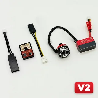
Furitek NanoModo Stock TX Plug & Play brushless system for Axial SCX30

Furitek NanoModo Stock TX Plug & Play · FUR-2762

Approx. build cost$120Build parts · USD
Controller & receiver
Uses stock controller (receiver included)
Lights
Connect with the included lead
Electronics
Motor and ESC arrive wired together
Water protection
Not rated
Tuning
Phone app
Shop the kit
View parts & setup

Upgrade to full brushless crawling and app tuning while keeping your original factory remote control. No extra transmitter or radio bundle required.

Main conversion

Furitek NanoModo Stock TX Plug & Play brushless system for Axial SCX30

Furitek NanoModo Stock TX Plug & Play system · FUR-2762

Lighting, adapters & mounting

Install without soldering · 7 steps
Before you start
  • Remove the stock motor screws carefully and retain the original hardware.
  • Verify battery plug, signal adapters, lighting harness socket type and BEC voltage before buying.
  • Keep the SCX30 stock motor, receiver and lights until the conversion passes its first test.
Battery → NanoPython ESC ↔ prewired NanoKomodo motor. Receiver channels: CH1 = Steering servo; CH2 = Throttle (NanoPython ESC signal). Join both stock light plugs through the included Y-lead into the matching powered micro port. NanoPython BEC defaults to 5.5 V (keep at 5.5 V for stock servo, switch to 7.4 V in app for HV servos).
  1. Make a photo first

    Photograph the stock receiver, battery polarity and both light plugs before removing anything. Disconnect the battery.

  2. Remove the original electronics

    Remove the stock motor screws carefully. Mount the replacement motor with the screws supplied in its kit. Keep the original screws together.

  3. Fit the new motor and set gear mesh

    Use the supplied 11T / 0.3 MOD pinion. Keep the motor wires clear of the spur gear. Follow the gear mesh check below before securing motor screws.

    Brushless Motor Gear Mesh Check

    Before tightening motor mount screws or driving, check gear mesh with two simple tests:

    1. Paper strip test: Feed a narrow strip of standard notebook paper between the motor pinion and spur gear while rotating the spur by hand. The paper should come out with clean accordion crinkles, not pinched flat, torn, or cut in half.

    2. Backlash check: Gently rock the spur gear back and forth with your fingertip. You should feel a tiny hair of play (backlash) without moving the motor pinion. Check this across a full 360-degree rotation of the spur to ensure there are no tight spots due to gear eccentricity.

    Warning: Too tight causes motor overheating, gear binding, and rapid battery drain. Too loose will strip the 0.3 MOD pinion or spur teeth under crawling load.

    RC motor gear mesh check

    Check motor gear mesh with the paper strip test and backlash check across 360 degrees to prevent gear strip or overheating

    Watch on YouTube
  4. Wire receiver: CH1 steering, CH2 throttle, CH3 lights

    Plug the stock steering servo into CH1 (Steering) and the pre-wired NanoPython ESC throttle lead into CH2 (Throttle). Join stock headlight plugs via the included Y-lead into the receiver.

  5. Connect the lights without soldering

    NanoModo includes a Y-lead that joins both stock light plugs to one ZH-1.5 receiver connector. Align the power and ground pins; the signal pin remains unused.

  6. Bind the radio and calibrate throttle

    The Furitek Micro SLT2 receiver binds directly to your factory Axial SCX30 SLT2 transmitter. Turn on the factory radio, power on the receiver, and confirm the solid link indicator.

    Furitek NanoPython Throttle Calibration

    Furitek uses Bluetooth app setup via Furicar:

    1. Turn on your transmitter and connect the truck battery.
    2. Open the Furicar app and tap connect to find the NanoPython ESC.
    3. Confirm brushless motor mode and calibrate throttle neutral in the calibration tab.
    4. Test throttle response; toggle motor direction in the app if wheels turn backward.
  7. Test before closing the body

    With wheels off the ground: verify neutral stop, steering direction, forward/reverse, headlights, and radio failsafe. To test failsafe, switch transmitter off briefly with wheels off the ground; the motor must stop immediately. Check cable clearance and ESC warmth. Only then tie up wires and close the chassis.

Furitek manufacturer video

Linked from the NanoModo product page

Watch on YouTube
Additional Furitek product video

Linked from the NanoModo product page

Watch on YouTube
Keep the factory lights

The SCX30 NanoModo package lists a joining lead for the two factory light plugs. Use the supplied connector layout; the motor and ESC arrive factory-wired together.

Technical specifications
Battery voltage
2S–3S LiPo7.4–11.1 V nominal
ESC current
20 A continuous50 A peak
Motor
NanoKomodo3450 KV
Servo power (BEC)
5.5 / 7.4 V5 A

2S and 3S describe the battery voltage. BEC is the separate power supply for the receiver and servo. Keep the factory servo within 4.8–6 V; the setup steps show the setting for this ESC.

FUR-2762 includes the stock-compatible SLT2 receiver with the pre-wired brushless system.

Crawling control
FOC motor control
Understand this conversion

Furitek FUR-2762 supplies a factory-matched micro receiver compatible with the stock SLT2 protocol alongside the pre-wired brushless power system.

Furitek: FUR-2762 Stock TX Plug & Play system
Read owner discussions

Owners wanting to keep their stock controller choose this plug-and-play package for seamless conversion without buying or carrying an additional radio.

Open the owner discussion
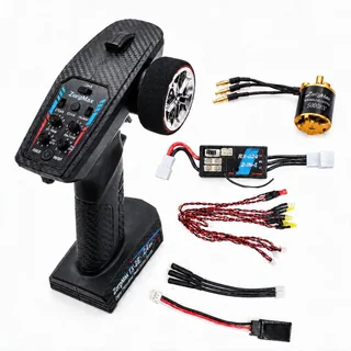
Zorgmax SCX30 2-in-1 combo, TX-8B radio, motor and LED lights

ZorgMax 2-in-1 Kit

Approx. build cost$60–$100Build parts · USD
Controller & receiver
Included in kit
Lights
Use the matching kit lights
Electronics
ESC and receiver share one module
Water protection
Not rated
Shop the kit
View parts & setup

The kit brings the motor, combined ESC/receiver and matched radio together. If the combined module fails, you replace that module rather than only the ESC or receiver.

Select the package with the motor, controller, receiver and lights.

Main conversion

Lighting, adapters & mounting

Install without soldering · 7 steps
Before you start
  • Remove the stock motor screws carefully and retain the original hardware.
  • Verify battery plug, signal adapters, lighting harness socket type and BEC voltage before buying.
  • Keep the SCX30 stock motor, receiver and lights until the conversion passes its first test.
Battery → combined ESC/receiver → motor. Steering servo → steering port. Use the matched radio and included lights. Fixed 5.0 V internal BEC safely powers the receiver and stock 5 V steering servo.
  1. Make a photo first

    Photograph the stock receiver, battery polarity and both light plugs before removing anything. Disconnect the battery.

  2. Remove the original electronics

    Remove the stock motor screws carefully. Mount the replacement motor with the screws supplied in its kit. Keep the original screws together.

  3. Fit the new motor and set gear mesh

    Use the supplied 11T / 0.3 MOD pinion. Keep the motor wires clear of the spur gear. Follow the gear mesh check below before securing motor screws.

    Brushless Motor Gear Mesh Check

    Before tightening motor mount screws or driving, check gear mesh with two simple tests:

    1. Paper strip test: Feed a narrow strip of standard notebook paper between the motor pinion and spur gear while rotating the spur by hand. The paper should come out with clean accordion crinkles, not pinched flat, torn, or cut in half.

    2. Backlash check: Gently rock the spur gear back and forth with your fingertip. You should feel a tiny hair of play (backlash) without moving the motor pinion. Check this across a full 360-degree rotation of the spur to ensure there are no tight spots due to gear eccentricity.

    Warning: Too tight causes motor overheating, gear binding, and rapid battery drain. Too loose will strip the 0.3 MOD pinion or spur teeth under crawling load.

    RC motor gear mesh check

    Check motor gear mesh with the paper strip test and backlash check across 360 degrees to prevent gear strip or overheating

    Watch on YouTube
  4. Wire receiver: CH1 steering, CH2 throttle, CH3 lights

    The Zorgmax combined unit has labeled ports: plug the 3-pin steering servo into the steering port (CH1) and headlights into the 2-pin light port. Throttle is wired internally to the motor.

  5. Connect the lights without soldering

    Use the lights and connectors supplied by Zorgmax. Its combined receiver is different from the HotRC systems.

  6. Bind the radio and calibrate throttle

    The Zorgmax transmitter and combined ESC/receiver are a matched system. Switch on the transmitter first, then connect the battery. If necessary, use the BIND instructions supplied with the kit.

    Factory Matched Radio Setup

    The Zorgmax transmitter and receiver are pre-paired from the factory. Turn on transmitter first, then connect the truck battery. If motor runs backward, flip the throttle reverse (REV) switch on the transmitter.

  7. Test before closing the body

    With wheels off the ground: verify neutral stop, steering direction, forward/reverse, headlights, and radio failsafe. To test failsafe, switch transmitter off briefly with wheels off the ground; the motor must stop immediately. Check cable clearance and ESC warmth. Only then tie up wires and close the chassis.

SCX30 motor and ESC removal

Shows a different brushless system; use for the mechanical layout, not the exact connectors

Watch on YouTube
Keep the factory lights

The reference build selects a package with matching lights. Confirm the lights supplied with your selected package, and use the ports labelled on its combined controller.

Technical specifications
Battery voltage
2S LiPo7.4 V nominal
ESC current
25 A continuous60 A peak
Motor
1621 outrunner5000 KV
Servo power (BEC)
5 V1 A

2S and 3S describe the battery voltage. BEC is the separate power supply for the receiver and servo. Keep the factory servo within 4.8–6 V; the setup steps show the setting for this ESC.

The documented ZorgMax Amazon bundle. Other storefront labels and package options may use different components.

Understand this conversion

The documented ZorgMax bundle supplies its own transmitter and combined ESC/receiver. The reference also names Pyfore and Flyueace storefront options; their exact package specifications must be checked separately.

Kit listing and selected package
Read owner discussions

In an October 2026 SCX30 owner discussion, a buyer reported smooth low-speed control and praised the kit’s value. Another owner said the Amazon price had risen after a sale. These are owner experiences rather than laboratory test results.

Open the owner discussion
Building a longer-term RC workbench
Wera Kraftform Micro 2054/7 metric hex driver set with pouch

Wera 2054/7 metric hex driver set

Wera 2054/7: 0.7, 0.9, 1.3, 1.5, 2, 2.5 and 3 mm hex drivers. Add the exact 0.050-inch driver separately for SCX30 hardware that needs it.

A few useful answers.

Do I need a new radio for a brushless conversion?

Check the whole package. The ZorgMax and SCX30 NanoModo paths include a matched radio system in the curated build. The generic, GACRacing and Hobbywing paths add a transmitter and matching receiver. A transmitter by itself is not a complete radio system.

Will the lights still work?

Yes, with the matching light kit or connections for the build. Furitek’s SCX30 kit includes a joining lead; the modular builds need a compatible harness and receiver adapters. Use the lighting instructions for both front and rear lights.

Is the displayed build estimate a single checkout price?

No. Modular builds combine parts from separate listings. The planning estimate helps you compare the full parts list; the store prices beside each part refer only to that listing. Choose one radio route and check the actual package, delivery and taxes at checkout.

Does brushless mean I should use a higher-voltage battery?

No. Motor type does not establish a safe battery voltage. Use a battery supported by the exact ESC and motor combination, and separately check the receiver-power setting for your servo and lights.

This guide compares curated component combinations. Check the selected kit version, connector layout and included parts before ordering.